Background: Pulse Coupled Oscillators
Reins-MAC builds on the literature of Pulse Coupled Oscillators
(PCOs), which is inspired by firefly behavior. Each beetle
periodically emits a light. Other fireflies observe these flashes
and alter the timing of their own flashes, eventually yielding a
unison blinking of the whole swarm. Formally, the periodic
behavior can be described as a cyclic oscillator manifest
as a phase variable that (i) assumes a value in a
given range, e.g., [0,1), (ii) increases linearly over time
and (iii) resets to the first limit when the second is
reached. To mimic the flash of a firefly, resetting the phase
variable can be combined with a pulse that is essentially a
notification of the reset.
In fireflies, periodic pulsing and observing others is not
sufficient to produce synchrony. This coupling is achieved by
either actively anticipating or delaying the individual pulse.
Mathematically, this means that the phase variable of a firefly is
no longer a constant, linear function over time, but it exhibits
spontaneous changes in response to observations. The rules
driving these changes are captured in a coupling function
that establishes the phase variable at which the flash will occur
in the next oscillation round.
A distributed problem that can be reduced to the PCO scheme is
pulse scattering, whose goal is to obtain
pulsing schedules where all the nodes that can hear each others
beating are evenly spread throughout the oscillation period. A
simple but effective solution is to distance the local pulse as
much as possible from the surrounding ones; this is achieved by
placing the beating almost exactly in the middle between two
adjacent perceived pulses.
Reins-MAC TDMA Scheduling
Slot Allocation. We approach slot size selection and slot
allocation by noting the similarity between this communication
problem and that of pulse scattering. Consider the simple case
when all nodes are within communication range. Nodes spread their
pulses evenly throughout the frame, and if a transmission slot for
a specific node is defined to begin at the moment at which it
pulses and end when the next node pulses, a TDMA schedule
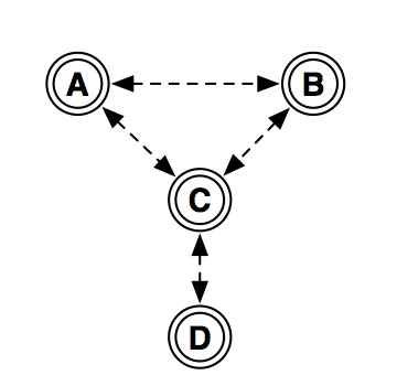
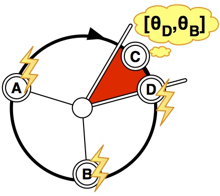
emerges. Consider directly applying such an algorithm in a
multi-hop network. While node C in Figure 1 will scatter with
respect to both A and D, because A and D are not within range,
they do not scatter with respect to one another and their slots
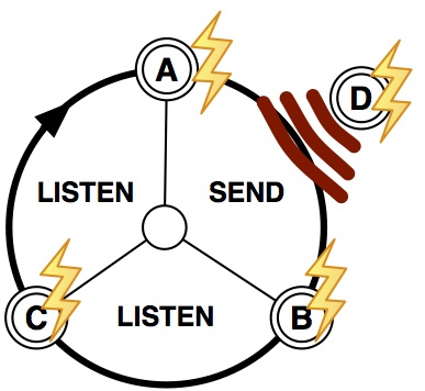
may overlap. Simultaneous transmissions from A and D will
overlap, causing collisions at C, as shown in Figure 2. This issue
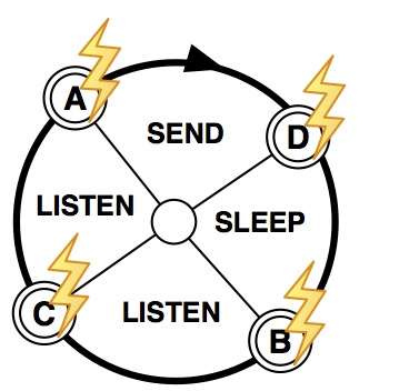
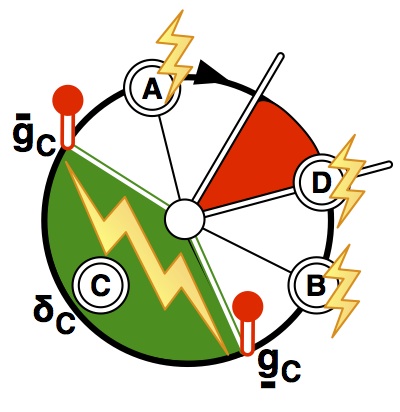
is solved by applying pulse scattering with a horizon of 2 hops as
shown in Figure 3. When the node's own pulse fires, it can
transmit; when a 1-hop distant pulse is received, the node listens
for incoming transmissions; when a 2-hop distant pulse is expected
the node sleeps to save energy, as no communication involving it
is possible.
Politely Join the Schedule. We first recall that no
synchronization is required in the solution presented above. In
fact, a node wanting to join the system can trivially learn the
current communication schedule by listening to the pulsing of its
neighbors, and independently decide the best placement of its own
pulse. However, this solution does not avoid collisions with
ongoing communication. Therefore, we adopt the approach employed
in classic TDMA solutions, allocating a coordination slot, common
to all schedules. Augmenting our MAC-solution with such a
synchronized slot is trivial: we simply require nodes to pulse
twice. One pulse is controlled by the scattering equation as
defined previously, while the other is updated according to a
synchronization coupling function, e.g., align the local pulse to
the average of the heard pulses. Notification of both pulses is
combined and transmitted at the beginning of the assigned
transmission slot. The synchronized pulse identifies a small,
fixed size slot, shown as a shaded region in Figure 4, during
which all nodes must listen, and any node can transmit using a
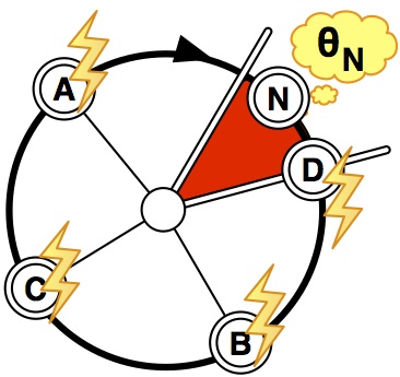
simple contention-based access approach. For a node to join the
schedule, it transmits in the control slot a deferred pulse
indicating its preferred location in the schedule. All
nodes incorporate the pulses indicated in the control messages
into their schedules, and after a stabilization period, the new
node can begin to transmit without disrupting ongoing
communications.
QoS Provisioning in Reins-MAC
Latency Control. In the scheduling solution described thus
far, the sequence of node pulses is fixed. This sequence affects
latency, therefore enabling changes in the sequence of node pulses
is the key to support latency constraints. Our solution is simply
for a node to remove itself from the schedule, then re-enter the
schedule at its desired location, using the control slot described
previously. This is shown in Figure 5 as node C removes itself
from its original location between A and B, and uses the control
slot to announce its new, desired position between nodes D and B.
Bandwidth Reservation. The bandwidth available to each node
is constrained to its own slot size. Therefore, Reins-MAC allows
each node to increase the single, assigned slot to the size
requested at run-time. To accomplish this, we give the pulse
a duration in time, delimiting the beginning and end of the
pulse with guarding phases, spread equal distance from the
center of the pulse. This guarding phases act as actual pulses for
the other nodes in the schedule, which scatter accordingly, as
described for slot allocation. As depicted in Figure 6, by
extending the pulse duration of C to begin at the first guard and
end at the second, the slots of A and B shift, leaving a slot that
provides the requested bandwidth guarantee to C. In the example,
the total reserved duration must be less than the distance between
A and B, as placing the guards beyond these limits results in
incorrect pulse scattering.